
I've been going to Electromagnetic Field ever since it started, way back in 2012. At each festival, each attendee is given a cool badge; a badge that is often a small microcontroller with a bunch of sensors and lights to play with. There have so far been 7 badges, each more different than the last. If you've never been to a hacker conference before, this sort of thing has been going on for a while. DEF CON, for instance, is quite famous for its badges. There is one problem though; quite often these badges just end up in a drawer somewhere, forgotten as the next shiny dev board comes out1.
I've set myself the goal of using every single EMF badge for something useful or fun before the next camp comes around. Now I have used two of them in projects before (a doorbell and the decide-o-tron), but I'm going to start from scratch. And I'm going to start with the badge I think is the most difficult - the 2014 one. But, I've found the perfect project for it - beescales!

But what are bee-scales and why would you want them? Do we weigh each individual bee?! Are we fat-shaming our furry friends?
One of the things about bee-keeping is that it is very seasonal. Throughout the year, there are different concerns and things we need to take care of. In winter, the big worry is whether or not the bees have enough stored honey to get them through the cold when there are few flowering plants around. The bees basically bunker down and keep warm, reserving their energy. Now, as good beekeepers. we don't want to open up the hive if we don't need to, especially when it's cold outside. So we weigh the hive to get a sense of how many bees and stores are inside. Each week, we weigh and watch for trends. If the weight starts to get too low, we can top up their supplies with fondant.
We used to weigh the hives using an electronic luggage scale. We'd hook under one side of the hive, raise it up, take a reading, then do the same on the other side. Add the results together to get a rough reading. Sadly, our luggage scale broke. An analogue, spring version was little better. I figured I could make some electronics scales. Funnily enough, such a product exists, but while they are reasonably priced, I figured I could make my own.
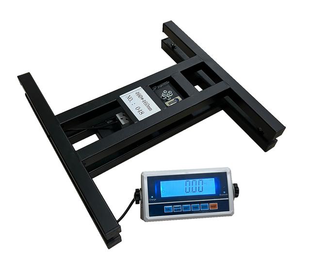
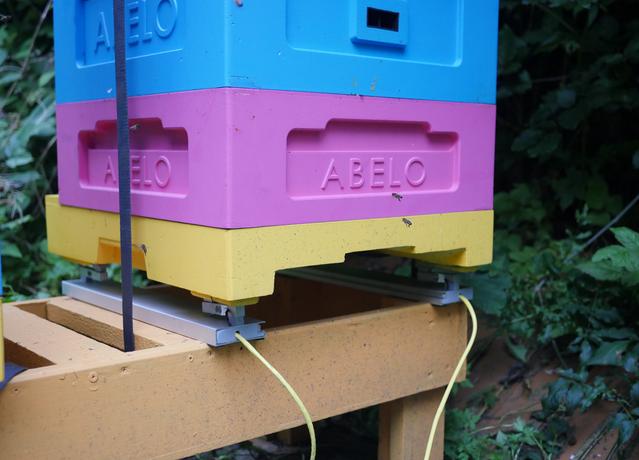
The trick with bee-scales is they need to be in two pieces. The reason being is the centre of the hive has a mesh at the bottom to allow the bees to remove waste, regulate heat and so we can check for varroa. We can't cover it up so we need two rails.
The trick to making electronic scales is the load-cell. Load cells are built around something called a strain gauge. The cell itself is usually some form of aluminium or steel block with a strain gauge somewhere inside. When a weight is placed on the cell, it deforms the strain gauge which changes its resistance. This resistance is pretty small however, so they are often found in groups of four, called a Wheatstone Bridge. These four resistors are balanced when an excitation voltage is sent into them. However, if one changes as it's deformed, the voltage measured across the bridge will change. This is what we are looking for. Every load-cell has a maximum weight it can tolerate.
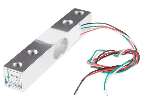
The first type of load-cell I found look like the one pictured above. They have 4 wires and come with an individual HX711 amplifier. To set the cell up, the bar needs to be attached at one end to the base with a certain amount of clearance. The weight is then placed on top at the other end. The 4 wires are the ground, excitation voltage (typically 3.3V or 5V) and the two points where we measure the voltage and therefore the force. The ones I found can take up to 20Kg each, which should be enough for our purposes.
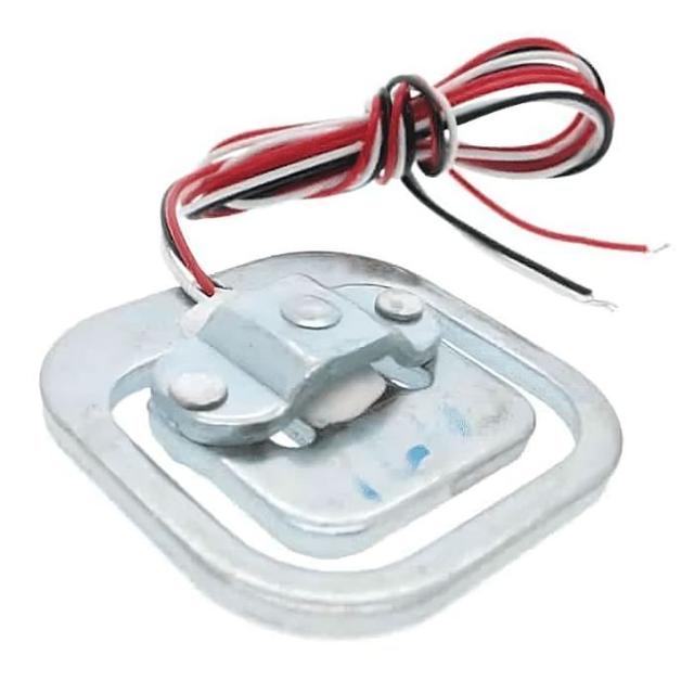
The second kind of cell I found has only three wires. These are designed to be used either as a pair or a pair of pairs and can deal with larger loads. At first I wasn't quite sure about them, but in the end, they seemed to be the better choice for this project. These cells don't have their own Wheatstone Bridge inside them, therefore they need to be wired up like one. The diagram below shows how these kinds of cells should be wired:
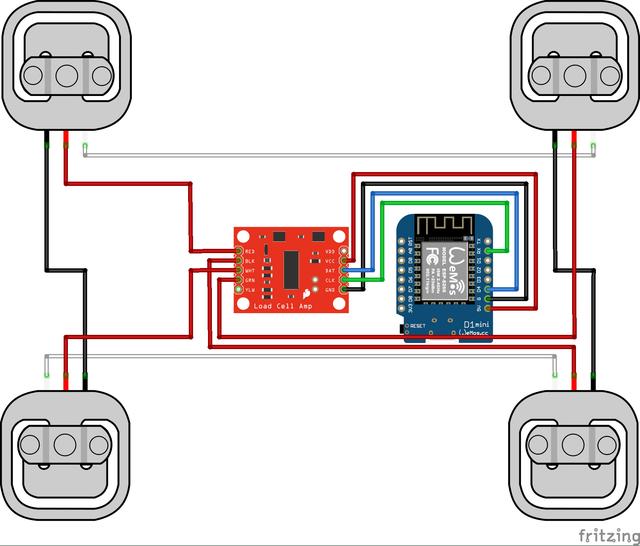
This website describes how to link a load-cell to a HX711 amplifier and hence, into your Arduino.
I think it's fair to say that of all the EMF badges, this one is perhaps the most difficult. It was manufactured by Ragworm who have long ceased to be, the ciesco radio isn't in production anymore (and I don't think the datasheet is too easy to find either) and I found the split approach between being an arduino and a sort of rtos hybrid a little confusing. I'm not sure all of the hardware on this badge has ever been used (but I could be wrong). This was the second badge attendees got to play with and an ambitious step forward.
The key thing for this project though, is that it has a screen and all the usual arduino pins. This means we can use arduino (or arduino-like) code and libraries to drive the pins, to read the load-cells, to display the weight on the screen.
Now before any of you say "but why don't you just link the loadcells to an ESP32 or LoRa device and send out MQTT messages to your phone or similar?", I've got an answer. Well, a couple in fact. One of the things we have to do is tie down the hives, in case of bad weather. This would affect the readings, so we need to go outside and loosen the straps before taking a reading. Secondly, we'd have to setup a long lived power source out in the meadow. While this is something I do want to do, I don't want to introduce too much scope creep at this stage. I'm on a ticking clock! These scales need to be done before Winter comes!
I previously mentioned that one can program this badge in (at least) two ways: as a normal arduino or as an arduino like device running with FreeRTOS (or a modified version). What is FreeRTOS you ask? RTOS stands for Real-time Operating System. This small operating system provides a few basics, but the main one is process management with a guarantee that operations will take a known and regular amount of time. RTOSes are used fairly often in embedded and critical systems. For EMF, having a text display that could receive updates but also listen out for user input at the same time, having an RTOS was one way of solving that problem.
To make things friendlier for all the attendees, the RTOS could be built and modified inside the arduino IDE on your desktop. If you are familiar with C and C++, it'll all look quite familiar. Ten years later the code in the git repository still works fine! The EMF Camp Wiki has all the details on the 2014 badge, including instructions on how to recover the badge if you brick it (which I certainly did!).
Let's start with the physical build. I found a couple of pieces of aluminium extrusion in my pile of bits. These came off an Ikea wardrobe I think. They are the right width and there's just enough of it to make two pairs. Excellent! Cutting aluminium is no big deal with a metal blade on your hacksaw. Drilling is also easy enough. Once the edges are filed down, it's ready to be used.
The bar-like load cells I managed to mount using long bolts and a set of 3D printed spacers to get the cells the correct distance above the extrusion. I also 3D printed some 'feet' for the ends of each bars so that the cells wouldn't dig-in to the hive.
I decided to use ethernet cable for all the wiring. I had a bunch of cables lying around that I didn't need. Since it's insulated I figured it might last long enough outside to be useful.
The next step involved the load cells and the amplifier. I wired up each cell to it's amplifier, then used some heatshrink to encase both the wires and the amplifier, making sure I got everything in the right order. An important point - the wires coming off the load cells are very thin indeed! They are easy to break, the insulation melts very easily and if you pull them too hard they'll come away from the loadcell and you'll never get them back on! Yes, this did happen!
With everything soldered together, encased in heatshrink, the final element was to close off the ends of the extrusion. I 3D printed a couple of endcaps so that no creepy crawlies could get in and nibble on the electronics.
The second version of the cells was built a little differently. I ordered some ethernet breakout boards from Ali Express and soldered these to some Vero board. This means I can unplug and the scales easily if I need to rewire or replace anything. It also saves me from having to solder ethernet wire to the badge directly.

The second type of load-cell isn't built to be screwed down and cantilevered like the first time. We need to mount them on the extrusion, preferably slightly above the extrusion so the central part can be pressed down. Fortunately, Thom Dietrich on Thingiverse has designed the perfect mount. These things are great, with a little tunnel for neatly organising the wires. I printed off four of these and screwed them down to the extrusion.
We need some sort of library to read the values coming from the HX711 amplifier. I found this library by Olav Kallhovd works quite well. Before I finished the bee-scales completely, I tested one of the load cells with the HX711 on both a normal arduino and the EMF badge, with the example in the repository.
You only need 4 pins for the HX711: ground, 3.3V, dout and sck. The last two are digital pins.
To build the software for the EMF badge, one needs to pay close attention to the instructions on the EMF wiki. The first thing to do is to checkout the git repository. Once this is checked out, fire-up the Arduino software, then set your Arduino folder to the Mk2-Firmware folder. I found it much easier to use the older 1.8.x version of the Arduino IDE for this. Restart the IDE and you should have the option to build for the Tilda Mke using the 0.333v of the RTOS core. I had no luck programming the badge using the Arduino core.
There are a number of what the designers called apps inside the firmware. These are like small sub-programs that are launched from the main menu of the badge. HelloWorld is one such app and it's a good starting point for a program. I duplicated this app code, called it beescales and proceeded to add the HX711 example and pull in the HX711 library. To my surprise, it worked like charm! I could even write the results to the main screen, just as I'd hoped.
This is one of the fiddly parts of the process. We need to find the offset and scale for the load-cells. First, we record the result with no force applied - the tare weight. Then, we add a selection of weights and record the new values. From these values we can find the scale, or how much does the reading change when a certain weight is applied. For example, let's say we get a value of 1000 when no weight is applied. If we then apply 1Kg and get a score of 3000, then a weight of 2Kg and a score of 5000 we know the offset is 1000 and the scale is 2000. We are assuming that the scale is linear and that it doesn't change depending on temperature (at least, not so much that we care).
This is more of a faff in the first version of the scales as we have four individual load-cells to calibrate. We then need a bit of extra code to sum all four readings together, then calibrate again. The second version of the scales is much easier, as we calibrate all 4 cells in one go.
All of the electronics are housed in a plastic, outdoors electronics box. These things are sealed against wind and rain. When I go out to weigh the bees, I take a little USB li-poly lipstick style battery. This is more than enough to power the badge and there's no need to leave a battery out in the box when I'm not weighing (of course, when I'm using a radio link, it'll be different).
The first version of the scales is a little precarious! The hive does sit on the scales reasonably enough, but it's not super ideal. The second version feels a bit more sturdy. The first hive (called Freddie) weighs in at around 43Kg, which is super impressive! This is quite a healthy weight for a poly-hive going into winter. The second hive (called Brian) is a little more concerning at only 33kg. This one will need a little fondant to help it through I think.
Why Freddie and Brian? Well, I'll leave that as a little game for you all to figure out.
We've been weighing the bees for a couple of months now, and it is much easier. I don't have to suit up, or wear gloves or anything like that. I don't need to move the hives or bother the bees in anyway - just loosen the straps, take a measurement, then tighten the straps again.
As far as I can tell, this might be the only honey related use of the Tilda Mke badge. I've not seen too many projects using this badge. I quite like the approach of using an RTOS, though I think in trying to get it to work with the Arduino IDE might have confused matters a little, though at the time I suppose there was little option. Arduino is still one of the easiest, most polished ways of getting into microprocessors and electronics. It's just a shame I can't get that Ciesco radio on the back of the badge to work. I recently found out I had a breakout board for such a radio, lying around in one of my many bits boxes. Maybe that's the next version?
