I've been working on and off with FPGAs for a few years now. I've come back from a break to get started on a new project that begins with a new board - a HDMI compatible PMOD for the Arty developement board. I have to say 'compatible' apparently, because the HDMI forum don't like it when you just say something is HDMI. With that little annoyance out of the way, here's the details for my little board in case you want to come up with your own.
If you just fancy the KiCAD project and the gerber files, you can check it all our from my github project.
A PMOD is basically, a couple of 2.57mm sockets, 2 rows of 6 pins for a total of 12 pins per socket. Quad sockets also exist apparently, though I've not seen any. It seems to be common on most FPGA development boards. Designed by Digilent, this open standard allows us to connect directly to the pins of the FPGA. We can add a number of peripherals - from VGA sockets to ethernet to CANBUS.
VGA is not a bad standard in my opinion. If you need to get something visual out of your silicon, it's a reasonable option. However, most modern screens use something like DisplayPort, HDMI or similar. It'd be nice to use my FPGA dev boards with a modern screen, so using a PMOD makes sense, if I don't want to spend a lot of money on a Nexys development board
Each socket has two ground pins and two power pins, leaving 8 pins left over. This is perfect for HDMI which is comprised of four separate signals: channels 1, 2 and 3, and the clock. The eagle-eyed will notice that four is not equal to eight. That's because each signal is transmitted over two wires - differential pairs.
Differential signalling uses two lines. On one line the signal is inverted. At the receiver, this signal is inverted again and added to the original signal, amplifying the original. This helps with noise, allows longer cable runs and cancels out certain imbalances in impedance. To be honest, I know very little about this sort of thing, save that the pins come in pairs, and this is key.
The Xilinx Spartan 7 I'm using on the Arty has a number of differential pins. These are labelled as such and should go together. Now some of you might know that HDMI Compatible PMODs already exist. The problem is the signals don't match the pins on the PMOD. An example, the HDMI Clock signal will have a positive (clk_p) and negative (clk_n). These should map to a particular differential pair such as L11P and L11N. However, the pins on all the PMODs I could find just didn't match up.
I read the guide to arty pmods and the arty reference manual and found the pin mapping. Looking at PMOD B straight on the socket we have:
VCC GND C15 D15 E16 E15
VCC GND J15 K15 J18 J17
If we look at these pins, we can find which ones are positive and negative pairs:
VCC GND N P N P
VCC GND N P N P
This is great! We have 4 pairs. So we can lay out our signals as follows:
VCC GND C1N C1P C0N C0P
VCC GND CKN CKP C2N C2P
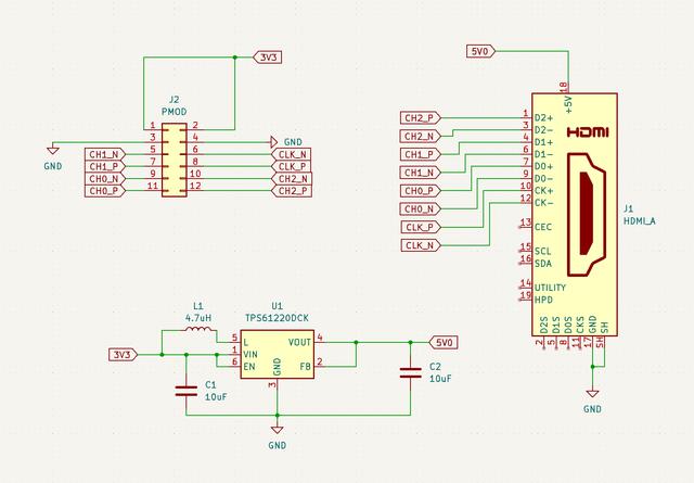
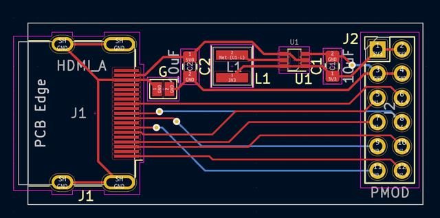
Now we have the pins setup, we can use a program like KiCAD to design our board. The HDMI connector itself has 19 connections but we are only interested in 10 of these. 8 signals, one ground and +5V power. This last one is a bit of a fly in ointment sadly. The PMOD runs at 3.3V so we'll need a little boost converter on our board. This isn't too tricky to design fortunately and requires 4 parts:
The full parts list is as follows:
I suspect I could have gotten these parts cheaper if I'd gone with RS or shopped around a little more. I didn't particularly design the board to be cheap to make but then there aren't many parts on there at least.
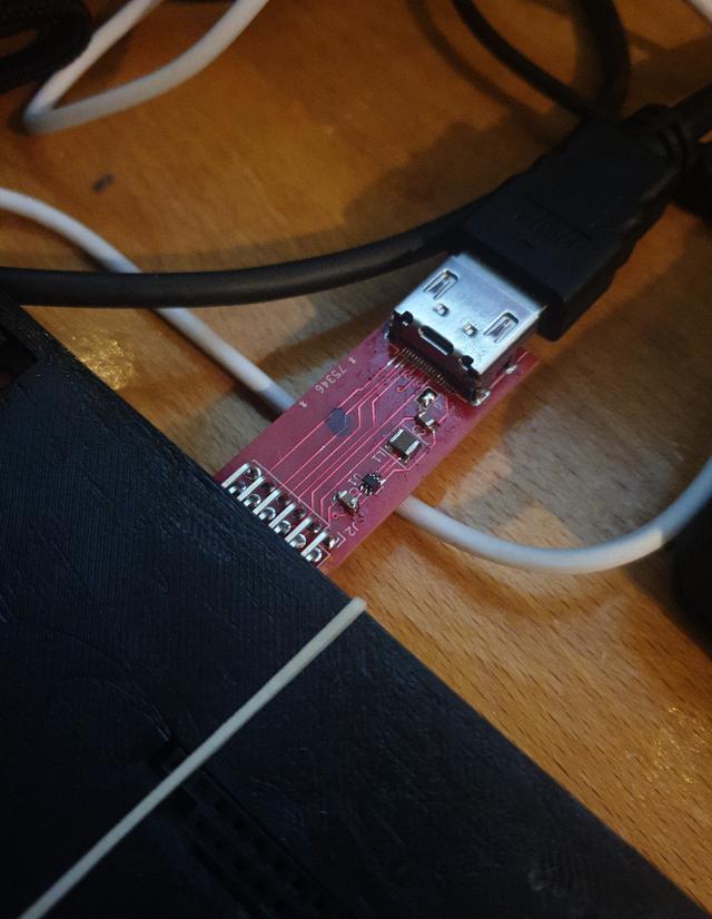
I got my boards made up by Dirty PCB over in Hong Kong. It takes a bit of time for them to arrive but they are cheap and the quality seems pretty good. Can't say I know more than that. For a simple board I think they are fine.
Soldering this together requires a bit of a steady hand. I have a two nibs on my soldering iron - a chisel and a fine tip. The HDMI connector can be tricky to line up; it has very fine wire connectors on the inside and four larger tabs. I've found that using bluetack to hold the socket in place then soldering the tabs seems to work. To solder the tiny connectors, I dump on a load of solder, then add a tonne of flux over the top. Taking some solder braid (or wick) I remove the excess solder with the braid and my chisel tip. Works a charm!
The other components I can hand solder with the fine tip. The regulator chip is perhaps the hardest. One can use the solder wick trick here if it doesn't go well.
Some folks may point out that other PMODs are available that are HDMI compatible(tm). The trouble is, the ones I bought weren't wired up properly for the Arty A7 PMOD; the differential pairs were not properly grouped for some reason. Not sure what that was all about, so I figured I'd just make my own.
If you are keen on learning more about FPGAs and all the cool things you can do with them, have a gander at Project-F.