I've started work with the Sea Mammal Research Unit (SMRU) over at the Scottish Oceans Institute, itself a part of St Andrews University. One of my first projects was to take a look at finishing the build of a couple of special sensor packages. These devices attach to something called a Soundtrap; a device that listens for the various sounds marine mammals make. These packages record things like orientation, temperature and depth. Combine these with the sounds and you can get a good picture of what is going on in the deeps!
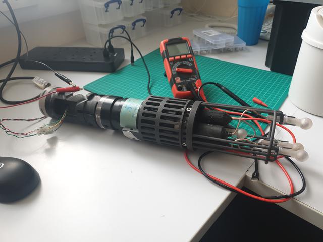
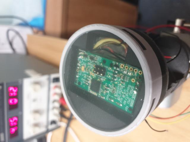
The whole system was designed by my colleague Jamie MacAulay. There are a number of versions of the hardware in operation - I was brought in to look at one of the older designs; we needed to press-gang some into service. The packages themselves attach to a soundtrap and the whole thing is encased in a 3D printed shell which is then thrown in the sea.
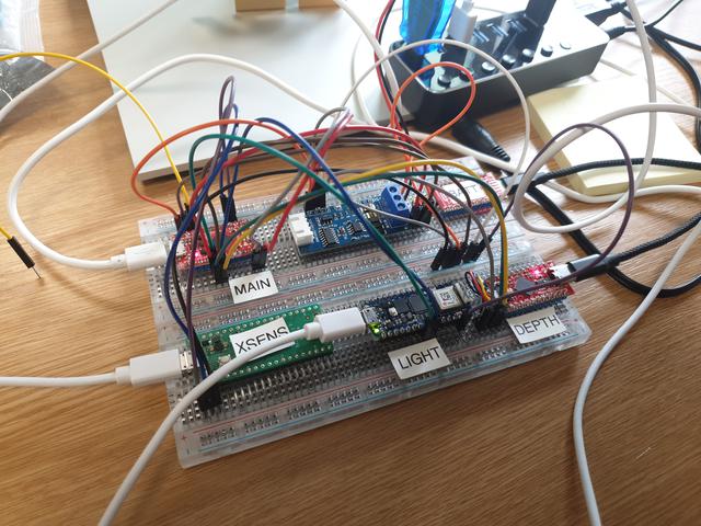
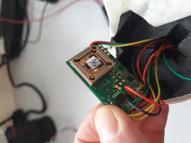
The sensor packages themselves are built around an Arduino, specifically the Sparkfun Pro Micro 3.3V board. Attached to this are a number of sensors for temperature and pressure (and therefore depth), light, battery levels and most important of all, orientation. The orientation sensor is one of the XSens lineup, the MTi-1 from XSens /Movella. This chip is quite the nice Inertial Measurement Unit (or IMU) and forms the core of the sensor package. With this working, we can tell the orientation of the hydrophones and therefore where the sound came from in relation to the Earth.
The main board itself isn't actually a Sparkfun Pro Micro. Rather, it is a custom, integrated board, based on the Pro Micro. It contains some of the sensors, such as the battery monitor, light sensor and battery charging chips, in addition to the processor - the ATMega32u4.
The casings that hold the electronics and sensors together are 3D printed by an external supplier and shipped back to us. These packages are coupled with the sound trap and placed inside a further 3D printed outer casing, which holds all the sub-assemblies together.
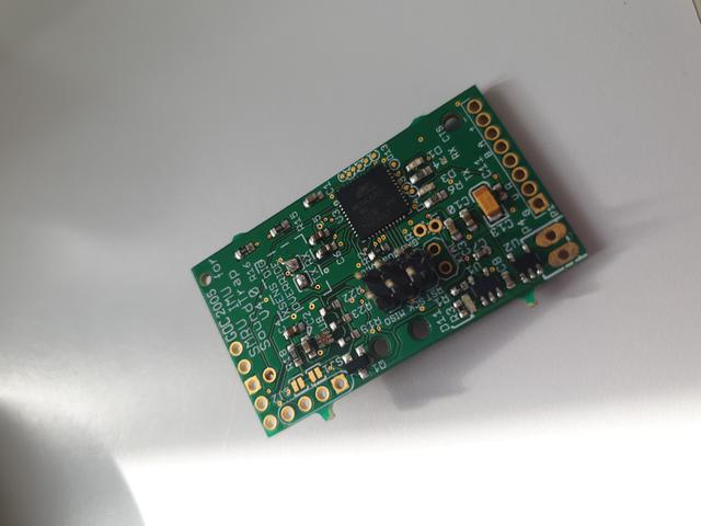
I came on board (hah!) to look at bringing back some of the older sensors that were missing a couple of parts. Thanks to the chip shortage, the boards we received from the manufacturer were missing a specific component - a chip for monitoring and controlling the batteries. I managed to find a MAX1704 chip that fit the bill and were in stock. The issue of course is managing to solder such a small chip, which just so happens to come in the TDFN package. This chip has no leads and is therefore not designed to be hand-soldered.
I thought about baking it in the oven or using a hot plate, but that would potentially remove the other components, especially as the board is populated on both sides. In the end, I settled on the following technique: mask off the board with kapton tape, solder the pads with a tiny amount of solder, flux, then place the chip on top. Use a heat gun with a tiny nozzle to get the solder to flow. If you do it right, the chip will be pulled into the right spot. This seemed to work quite well.
Electronics and the sea really don't mix! Salt water is just about the worst. Add to that increasing pressures and you've got a disaster waiting to happen. If that wasn't bad enough, putting anything in the sea is time consuming and will devour all but the biggest budgets. Any mistakes will be much more costly. I reckon the sea is second only to space in how difficult it is to operate in. We have to harden our electronics, literally!
This was the first time I've heard the word 'potting' applied to electronics. In short, a resin-like compound (I'm not sure what) is poured into and over the package, completely sealing it. Once the package is potted it is pretty much impossible to get at the electronics again. The process (from what I can remember) involves careful pouring, followed by constant swirling on a moving plate in order to encourage all the air to work it's way out. Any air pockets could cause issues at depth.
A couple of times, some of my soldering wasn't quite up to snuff, or one of the wires had became caught and snapped during the potting process. We needed to dig out the potting compound using a milling machine and a hot soldering iron. Not a pleasant job at all!
It seems like quite an art, getting a good pour. A number of channels needed to be milled and some holes drilled in the 3D printed casing in order to get the compound to flow correctly.
The firmware itself needs to do a number of things - read the sensors, write to the soundtrap, write to USB and check the state of the batteries. I came up with a flow/state diagram that described all the things the firmware needed to do and under what circumstances the state of the system would change - a finite state machine of sorts. I figured it was a good idea to know what state the system was in, simply by looking at a flashing LED. If one provided the correct inputs to change state, one could see and verify that things were operating as expected.
The sensor package needs to read all of the sensors and write these results to the soundtrap using the XBusMessage format. Custom firmware on the soundtrap would read these messages and record them to the SDCard inside the soundtrap itself. All communication with the soundtrap takes place over an RS485 connection. If the user plugs the sensor package into a computer, the same messages should appear over the serial connection. In addition, the XSens chip should accept certain setup commands over this serial link. The soundtrap itself needs to be continuously pinged to make sure it's still recording and accepting data. Finally, if the battery voltage or stage-of-charge goes too low, the system should enter a deep low power state.
The Arduino framework provides many of the libraries required, except for these dealing with the XSens chip - these we had to write ourselves, though many examples in C++ and Python do exist. One thing that is easier to do outside of the Arduino framework is messing around with some of the features of AVR chips. It turns out that inside the ATMega32u4 is a small oscillator that will reset the chip if a particular register is not reset within a certain time limit. This watchdog allows the system to be reset in case the firmware enters an infinite loop. Not a bad little feature. On the ATMega32u4 the maximum delay is 4 seconds, so the main arduino loop has to finish under this time.
We use the same bootloader as the Sparkfun Pro Micro - it's quite handy and seems to work well. It means we can use a variety of tools to program the board with the firmware - from the Arduino IDE to something more powerful.
I started looking at automatic and quicker setups for building the firmware. The first thing I came across was Arduino-cli. This little program wraps much of the IDE functionality but on the command line. You can download arduino libraries, build the firmware and flash to a device using just a command or two. It's handy as you can keep track of the libraries you might need, downloading as necessary with a single command.
While the Arduino CLI was fine, it was missing a few features, mainly any sort of testing framework. Not only that, I wanted to get a more complete build system together where I could run some static analysis tools like cppcheck and such. Secondly, it's a bit easier to use an external editor with platformio. While it's possible to do this with the Arduino IDE, it is a little bit cobbled together. Third, one can more easily use some of the fancy features of C++ and gain a bit more control. Finally, I wanted to try a couple of simulators in order to take the testing as far as I could go. Thanks to a tip-off from the UKRSE group, I became aware of platform.io.
Platform IO is a set of python scripts, servers and frameworks for unifying development across embedded devices. It's designed to integrate into Visual Studio Code but can be used on the command line just as easily. It supports a wide variety of embedded devices and comes with it's own test framework, as well as several utilities for simulation. It's build system revolves around the pio command and a configuration file - platformio.ini - which I believe is in YAML format.
The testing framework is pretty useful. Much like googletest or doctest, you can write short C++ programs, called with the command pio test. A whole set of assert functions are available to you. But what is really great is you can run these tests on both the host and target software using the bundled SimAVR.
When I thought about testing, I wondered if it was possible to test on the host hardware. It turns out, the answer is yes, thanks to SimAVR. You can download this project from github as a standalone, but it also comes bundled with platformio. As the name suggests, SimAVR simulates a number of Atmel AVR chips, including our ATMega32u4. In this way, we can run our tests on host hardware, thus taking advantage of continuous integration, later on down the line.
One problem exists with this particular approach - the ATMega32u4 has a USB to serial stack built in. This isn't simulated (I don't blame the developers, honestly! USB seems like a right faff!) so any Arduino like calls to Serial won't work. This messes up the tests unfortunately as these rely on communication over a serial line. The solution, I found, was to use Arduino Serial1, with the use of a special script that I've placed on github as a gist.
Running tests on the host machine is a good start, but there's no substitute for the real thing - sort of. In order to test the sensor packages more thoroughly, I decided to create a full test rig. This consisted of a Sparkfun Pro micro running the firmware, connected to a number of other development boards I found in the desk drawer. Each of these boards would simulate a particular sensor, responding in the same way as the real thing.
Thankfully, the all of the libraries we used are open source, so working backwards, one can write a software version of each sensor. Most of the sensors used I2C - a common 2 wire protocol (or maybe 3 if you count ground). The Arduino wire library comes in very handy here. Depth, battery and light sensors were all reverse engineered this way.
The XSens MTi-1 orientation board on the other-hand uses TTL serial and has it's own protocol using the aforementioned XBusMessage. It has a little gotcha in that the data stored in such messages, like Euler angles or Quaternions, are held in big endian order, unlike the AVR or x86 which uses little endian. It's fairly trivial to reverse the order but given that C and C++ don't have multi-byte types that aren't numbers, one has to be careful when making comparisons. The message format itself is well documented though and easy enough to simulate.
In the end, I used 3 sparkfun boards and two Raspberry PI 2040 boards, all programmed using platform.io and all wired in the same way they would be on the real sensor package. The only issue I had was with the simulated Light Sensor, which seemed to work very slowly for some reason. With the simulator in place, we could perform some testing - it's much cheaper to see how the firmware would respond to being 300m underwater using a simulated sensor than dropping it in the sea and then fishing it out again.
I've yet to figure out how to write integration and unit tests using this real hardware. It should be possible to write a more formal test that can be re-run as required. Unfortunately, I ran out of time before I got this far. At present, one can alter the temperature, pressure, battery and orientation values with reasonable ease.
Now that we have a way to build the firmware on the command line, as well as running tests and static analysis, we can roll all of this up into a continuous integration. We use gitlab at work, which has set of CI tools built in. I setup a runner on my desktop machine using docker rather than using the provided runners, mostly as a learning exercise. The process for using such a runner with gitlab is well documented. The only issue I came across was not knowing which packages needed installing on top of the base image.
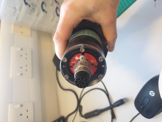
The soundtraps we use are designed by OceanInstruments.nz. They contain a set of hydrophones, the hardware to create sound files from these hydrophones, an SD card for storage and a set of batteries of their own. The subconn connector - a type of marine electrical socket - has 9 pins, 4 of which are used for a USB serial connection. The soundtrap records the sounds in it's own format, while the sensor package writes it's data to the soundtrap via an RS485 connection, also through the subconn.
Sadly, the software for the soundtraps is - shall we say - not the best. It is slow, prone to crashes and for some reason I've yet to understand - doesn't work on a Virtual Machine. I do (almost) all of my professional work on Linux and when I need a windows machine I prefer to use a VM, as I don't have a second machine in the office. I could dual-boot as I do at home but that's almost as awkward as walking a few minutes to the other side of the building to use the machine in the lab. I suspect it's something to do with the driver that gets installed. I'm told that all drivers for Windows need to be signed these days, which seems like a good idea. The latest Windows version referred to on the OceanInstruments website is Windows 7 which is no surprise. It's a pity as copying the data is a particular bottleneck in field operations.In an ideal world, the SDCards within the soundtrap would mount as a USB drive, so one could use Rsync or any other copying tool.
At some point, investigating the communication protocol would be a fun challenge. Something for later perhaps? ;)
I'm sure a few folks reading this might wonder why we didn't use Microchip Studio or similar? I think the reason is mostly speed and ease of use. Arduino is pretty accessible to these without a background in electrical engineering or software engineering. The sheer number of easy-to-use libraries really speeds things up. Many of these libraries will have had significant testing and while they might not be the most efficient in terms of memory use or speed, we have enough cycles and memory to spare on this particular project (although that might not be the case in the future).
However, the Arduino setup really did begin to cause problems as the project continued. The IDE in particular isn't really designed for serious development; it does certain things to the codebase without telling you, links external libraries in it's own way and had it's own naming conventions. It's designed more as a quick sketchpad, rather than anything too serious. When you need to keep track of external libraries, use a non-trivial build configuration, run external tools like cppcheck, run unit tests or any of the other more typical software engineering tasks, the IDE gets in the way. I liked the arduino-cli quite a bit but I would recommend that anyone starting a new embedded project should start with platform.io, even if you take advantage of the Arduino libraries.
I think the Arduino Libraries, bootloader and platform.io is the real sweet spot. I'm a fan of Arduino in the main, but it's great to be able to use the more well worn tools with the Arduino libraries in combination.
I've moved on from this project now, but it was a real eye-opener. I've worked on firmware before whilst interning at Voltsport. It's a different sort of game - much closer to the hardware. As a result, things like processor speeds, memory usage, watchdogs, timings and a whole manner of other concerns come to the fore.
Testing and testing and testing again is of paramount importance, especially with things that go in the sea. Always when you think you've done enough, stop, take a break and then do more! In an academic setting this can be really difficult to do as the incentives are to get as much data as quickly as possible and get the papers out. There is never enough time to do all the things properly it seems - a major concern in all disciplines across universities at the moment. Software engineering groups are popping up in universities around the world however, so there are options to share the programming load.
I'd certainly love to work on firmware again, now that I've found some excellent tools.