
Everyone loves the 80s right? Well, I certainly do - well, the revival anyway. There were certainly parts of the 80s I don't want to see again, but that's another post. Suffice to say, some of the technolgy, style and music is coming back in a big way. With the EMF Cybar and Nullsector just around the corner I decided around June to have a look at the Nintendo Powerglove and how I could modernise whilst still keeping it intact.
You can find all the code for this over at my github page. I'd also like to thank my nephew Sam for being very diligent with his soldering and helping with the research! :D

The powerglove was designed to be plugged into a NES. This means it really only has the basic NES control pad inputs - A,B, Start, Select and 8 directions. There are two parts to the glove system really. The glove itself and the frame-like sensor bar that contains a set of microphones. The frame itself picks up ultrasonic pulses from the glove in order to figure out how it's moving. So if the glove is inside this frame and it's all calibrated, you can move your hand up or down to generate the corresponding button-push on the controller.

I decided not to look at this part because I wanted to wander around wearing the glove. It also seemed a little beyond me as the technology inside these sensors and the box that connects them seems mostly analogue. There are very few digital components in here as I would know them. Some clever amp circuits and what not going on here.
The glove unit plugs into the main box, as do the arms of the frame. Looking inside this box there are what seem to be some amplifiers, shift registers and what not but the majority of connections from the glove bypass all of this circuitry completely. The only ones that don't appear to be related to the fingers, which we'll get into. The connector from the glove is a standard DB9 which gives us a place to start.
There is an excellent writeup of the NES controller protocol at https://tresi.github.io/nes/. You can also get a good idea of the history at http://mellottsvrpage.com/glove.htm.
The first step was to see which DB9 pins correspond to which NES pins. Looking at the main box we know that some are directly linked so all we need to do is take our multimeter and find the mappings with a little continuity testing.
So far, the mapping I've found on the DB9 connector look like this:
    1 - x (wiggle?)
    2 - GND
    3 - x (wiggle?)
    4 - x (wiggle?)
    5 - +5V
    6 - GND
    7 - LATCH
    8 - CLOCK
    9 - DATA
Turns out we can quite easily create a NES controller with an Arduino and some code that looks like this (thanks to this article)
/*
================================================================================

    File........... NES Controller Test Code
    Purpose........ To demonstrate how to interface to an NES controller
    Author......... Joseph Corleto
    E-mail......... corleto.joseph @ gmail.com
    Started........ 04/13/2016
    Finished....... 04/14/2016
    Updated........ --/--/----

================================================================================
   Notes
================================================================================
- The NES controller contains one 8-bit 4021 shift register inside.

- This register takes parallel inputs and converts them into a serial output.

- This code first latches the data and then shifts in the first bit on the data line.
  Then it clocks and shifts in on the data line until all bits are received.

- What is debugged are the button states of the NES controller.

- A logical "1" means the button is not pressed. A logical "0" means the button is
  pressed.

- This code shifts the first bit of data into the LSB.

- The order of shifting for the buttons is shown in the table below:

                Bit# | Button
                --------------
                  0  |   A
                --------------
                  1  |   B
                --------------
                  2  | Select
                --------------
                          3  | Start
                --------------
                  4  |   Up
                --------------
                  5  |  Down
                --------------
                  6  |  Left
                --------------
                  7  | Right
                --------------

- The NES controller pinout is shown below (looking into controllers
  connector end):
      __________
     /      |
    /       O 1 |   1 - Ground
        |           |   2 - Clock
    | 7 O   O 2 |   3 - Latch
    |           |   4 - Data Out
    | 6 O   O 3 |   5 - No Connection
    |           |   6 - No Connection
    | 5 O   O 4 |   7 - +5V
    |___________|

- Please visit http://www.allaboutcircuits.com to search for complete article!

================================================================================
  Updates
================================================================================
*/

//===============================================================================
//  Header Files
//===============================================================================

//===============================================================================
//  Constants
//===============================================================================
// Here we have a bunch of constants that will become clearer when we look at the
// readNesController() function. Basically, we will use these contents to clear
// a bit. These are chosen according to the table above.
const int A_BUTTON         = 0;
const int B_BUTTON         = 1;
const int SELECT_BUTTON    = 2;
const int START_BUTTON     = 3;
const int UP_BUTTON        = 4;
const int DOWN_BUTTON      = 5;
const int LEFT_BUTTON      = 6;
const int RIGHT_BUTTON     = 7;

//===============================================================================
//  Variables
//===============================================================================
byte nesRegister  = 0;    // We will use this to hold current button states

//===============================================================================
//  Pin Declarations
//===============================================================================
//Inputs:
int nesData       = 4;    // The data pin for the NES controller

//Outputs:
int nesClock      = 2;    // The clock pin for the NES controller
int nesLatch      = 3;    // The latch pin for the NES controller

//===============================================================================
//  Initialization
//===============================================================================
void setup()
{
  // Initialize serial port speed for the serial terminal
  Serial.begin(9600);

  // Set appropriate pins to inputs
  pinMode(nesData, INPUT);

  // Set appropriate pins to outputs
  pinMode(nesClock, OUTPUT);
  pinMode(nesLatch, OUTPUT);

  // Set initial states
  digitalWrite(nesClock, LOW);
  digitalWrite(nesLatch, LOW);
}

//===============================================================================
//  Main
//===============================================================================
void loop()
{
  // This function call will return the states of all NES controller's register
  // in a nice 8 bit variable format. Remember to refer to the table and
  // constants above for which button maps where!
  nesRegister = readNesController();

  // Slight delay before we debug what was pressed so we don't spam the
  // serial monitor.
  delay(180);

  // To give you an idea on how to use this data to control things for your
  // next project, look through the serial terminal code below. Basically,
  // just choose a bit to look at and decide what to do whether HIGH (not pushed)
  // or LOW (pushed). What is nice about this test code is that we mapped all
  // of the bits to the actual button name so no useless memorizing!
  if (bitRead(nesRegister, A_BUTTON) == 0)
    Serial.println("JUMP!");

  if (bitRead(nesRegister, B_BUTTON) == 0)
    Serial.println("PUNCH!");

  if (bitRead(nesRegister, START_BUTTON) == 0)
    Serial.println("DOOMSDAY ACTIVATED");

  if (bitRead(nesRegister, SELECT_BUTTON) == 0)
    Serial.println("WHY DON'T YOU MAP SOMETHING HERE?");

  if (bitRead(nesRegister, UP_BUTTON) == 0)
    Serial.println("...OR HERE?");

  if (bitRead(nesRegister, DOWN_BUTTON) == 0)
    Serial.println("PLAY WITH THE CODE ALREADY!");

  if (bitRead(nesRegister, LEFT_BUTTON) == 0)
    Serial.println("MAKE SOMETHING WITH THIS!");

  if (bitRead(nesRegister, RIGHT_BUTTON) == 0)
    Serial.println("GOOD LUCK WITH YOUR PROJECT ");
}

//===============================================================================
//  Functions
//===============================================================================
///////////////////////
// readNesController //
///////////////////////
byte readNesController()
{
  // Pre-load a variable with all 1's which assumes all buttons are not
  // pressed. But while we cycle through the bits, if we detect a LOW, which is
  // a 0, we clear that bit. In the end, we find all the buttons states at once.
  int tempData = 255;

  // Quickly pulse the nesLatch pin so that the register grab what it see on
  // its parallel data pins.
  digitalWrite(nesLatch, HIGH);
  digitalWrite(nesLatch, LOW);

  // Upon latching, the first bit is available to look at, which is the state
  // of the A button. We see if it is low, and if it is, we clear out variable's
  // first bit to indicate this is so.
  if (digitalRead(nesData) == LOW)
    bitClear(tempData, A_BUTTON);

  // Clock the next bit which is the B button and determine its state just like
  // we did above.
  digitalWrite(nesClock, HIGH);
  digitalWrite(nesClock, LOW);
  if (digitalRead(nesData) == LOW)
    bitClear(tempData, B_BUTTON);

  // Now do this for the rest of them!

  // Select button
  digitalWrite(nesClock, HIGH);
  digitalWrite(nesClock, LOW);
  if (digitalRead(nesData) == LOW)
    bitClear(tempData, SELECT_BUTTON);

  // Start button
  digitalWrite(nesClock, HIGH);
  digitalWrite(nesClock, LOW);
  if (digitalRead(nesData) == LOW)
    bitClear(tempData, START_BUTTON);

  // Up button
  digitalWrite(nesClock, HIGH);
  digitalWrite(nesClock, LOW);
  if (digitalRead(nesData) == LOW)
    bitClear(tempData, UP_BUTTON);

  // Down button
  digitalWrite(nesClock, HIGH);
  digitalWrite(nesClock, LOW);
  if (digitalRead(nesData) == LOW)
    bitClear(tempData, DOWN_BUTTON);

  // Left button
  digitalWrite(nesClock, HIGH);
  digitalWrite(nesClock, LOW);
  if (digitalRead(nesData) == LOW)
    bitClear(tempData, LEFT_BUTTON);

  // Right button
  digitalWrite(nesClock, HIGH);
  digitalWrite(nesClock, LOW);
  if (digitalRead(nesData) == LOW)
    bitClear(tempData, RIGHT_BUTTON);

  // After all of this, we now have our variable all bundled up
  // with all of the NES button states.*/
  return tempData;
}
This gets us most of the way there, but there is a problem - well, two actually! The index finger and thumb!

The thumb and forefinger have some flex sensors in them and they seem to translate to A and B buttons respectively. If you were being fancy you could probably get an analogue reading out of that and properly map the finger positions. However, this would mean really taking apart the glove and adding extra hardware which I didn't have time nor inclination to do. So I figured I'd settle with just the on/off output for each digit.
The problem is I couldn't make them work at all, and when I stumbled on the solution, it wasn't the most reliable. This is where the actual hacking starts - trying everything you can think of till you get the result you want.
I tried everything I could think of but in the end, it seemed that one of the lines, when brought up to +5V and then down again would wake up the finger sensors, but then all the other buttons would return random values. Very strange! If one brought it back to ground it still stayed random, but occasionally, it would settle back down again.
So I added a line that wobbles ports 1, 3 and 4 on the DB9 connector and that seemed to be the most consistent. Occasionally the A and B buttons will activate without being pressed, but for the most part, this wobble bit in the code seems to work quite well.
UPDATE some of the comments on Reddit suggested I post the final code, describing the wiggle and what not so I've done that here:
/* INITIALIZATION */

int flex = 12; // set the wiggle pin
int latch = 5; // set the latch pin
int clock = 11; // set the clock pin
int datin = 8;// set the data in pin
//int glove_power = 22;
byte controller_data = 0;
int ledpin = 13;
bool init_glove = false;

/* SETUP */
void setup() {
  Serial.begin(9600);
  pinMode(latch,OUTPUT);
  pinMode(flex,OUTPUT);
  pinMode(clock,OUTPUT);
  //pinMode(glove_power, OUTPUT);
  pinMode(datin,INPUT);
  pinMode(ledpin, OUTPUT);

  delay(60);
  //digitalWrite(glove_power,HIGH);
  clear();
}

void clear(){
  digitalWrite(latch,HIGH);
  digitalWrite(clock,HIGH);
  digitalWrite(flex,LOW);
}


void controllerRead() {
  controller_data = 255;
  digitalWrite(latch,LOW);
  digitalWrite(clock,LOW);
  delayMicroseconds(12);

  digitalWrite(latch,HIGH);
  delayMicroseconds(12);

  if (digitalRead(datin) == LOW) {
    bitClear(controller_data, 0);
  }

  digitalWrite(latch,LOW);
  delayMicroseconds(6);

  for (int i = 1; i < 8; i ++) {
    digitalWrite(clock,HIGH);
    delayMicroseconds(6);
    //controller_data = controller_data << 1;
    //controller_data = controller_data + digitalRead(datin) ;
    if (digitalRead(datin) == LOW) {
      bitClear(controller_data, i);
    }
    digitalWrite(clock,LOW);
    delayMicroseconds(6);
  }
}

void loop() {

  if (controller_data == B11111011 && init_glove == false){
    digitalWrite(flex,LOW);
    digitalWrite(ledpin,LOW);
    delay(12);
    //digitalWrite(flex,HIGH);
    init_glove = true;
  } else {

    digitalWrite(flex,LOW);
    digitalWrite(ledpin,LOW);
    delay(12);

    digitalWrite(flex,HIGH);
    digitalWrite(ledpin,HIGH);
    controllerRead();
  }
  //flexRead();
  //digitalWrite(flex,HIGH);

  Serial.println(controller_data, BIN);

  //for REFERENCE:
  //UP = 11110111
  //DOWN=11111011
  //LEFT=11111101
  //RIGHT=11111110
  //SELECT=11011111
  //START=11101111
  //A=01111111
  //B=10111111

  delay(30);

}
When you plug in the Powerglove, it won't work first off. You need to press the Start button before it will send data back. It's said that you should wear the glove with your fist clenched before you press start, then release after you've pressed in order to get a good calibration. This seems to help a little with registering the finger presses correctly.
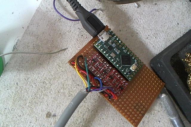
Back in the day, there was a very handy and cheap USB board called the minimus. A few years back I used this board on a similar project to covert a megadrive pad to USB. Sadly, I don't think one can get hold of them anymore so I moved over to everyone's favourite Arduino-based USB thingy, the teensy. Yep! These little boards are great and simple, and if you need something doing quick, this is the board to use. They are a little more expensive however, but they do work well.
I bought a couple of the new teensy LCs as they are the cheapest and have all the things I need. One thing I forget to notice is that it works on 3.3V only! This is a bit of a problem as the Powerglove runs off 5 volts. Fortunately I had a couple of sparkfun level shifters around that work pretty well. That got me out of a bind. I also had a spare Teensy 2.0 that is 5V tolerant, so I could rebuild two gloves - one for me and one for Charles, my friend and head of the Cybar project.
Annoyingly, I can't seem to setup the Teensy LC or 2.0 as just a gamepad. I need to go for a flight joystick instead. It's overkill but at least it works. Generally, the D-Pad takes the form of a hat - the little wobbly 8 directional button you get on fancy flight sticks. The same is sort of true with X-Box and playstation controllers when you are running emulators, so at least it's reasonably consistent.
Solder it all up, add a USB extension lead and boom! You've got a tidy little unit that plugs into the DB9 of the powerglove and the USB socket of your PC. What I like about this build is you don't need to mess with the inside of the powerglove at all. The only internal change I made was removing the live wire to the ultrasound emitters on the glove. They make a bit of a noise and as we weren't using them, I figured we could do without.
What better way to test the powerglove than to play Kung Fury, the videogame.
And just to finish it off, a shameless pose like the Eighties never died! :D