
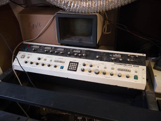
Over at HacDC they have the remains of a scanning electronic microscope. I've no idea what state it is in, but apparently it was found in a shed, outdoors or something! Anyway, apparently the pump works and the schematics for the board have been tracked down, so one of the more brave members of the hackspace is having a go at making it work. She asked me if I fancied reading the ROM chips from the machine and handing over the dumps. Figured that would be fine.
Some of you might have watched the TV series, Halt and Catch Fire? If not, don't worry, I won't spoil it much. Basically, a couple of the lead characters decide to read the bios out of the latest IBM machine. It's quite a dramatic moment, but the reality is perhaps somewhat more sober. Anyway, the process they had was quite involved, as it was the eighties after-all. Nowadays, we have things like the Arduino Mega that has enough digital input pins to read a ROM with ease.
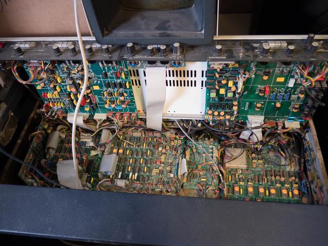
There are quite a few ROM chips inside the SEM. I figure it was most important to take photographs of everything before I started prizing out each chip. Some of them were pretty tough, and one of the sockets came apart. Another chip has a couple of corroded legs that just snapped - so that one is very dead. No going back now.
I practiced on an old Intel d2716 to begin with. The trick is to provide an address on the address pins, marked A0-A10 and read out the nice byte on the 8 output lines, D0 to D7. If you notice, the chip has a sticker over the centre. Turns out, these ROM chips could be erased by shining ultra violet light through the hole in the centre. I had no idea! So it's important the centre of the chips be covered up.
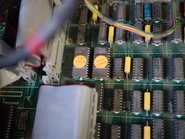
Most of this work is based on the excellent writeup by The Oddbloke Geek Blog. I've taken his approach and modified some of the code to work with the chips I'm using. The d27128 he refers to is a much larger ROM from the BBC micro. The ROMS in our SEM come in two varieties: 25L32 and 2516.
The first thing to do is find the datasheets. As far as I can tell, both of these chips are made by Texas Instruments, so tracking down the datasheets was not too much trouble:
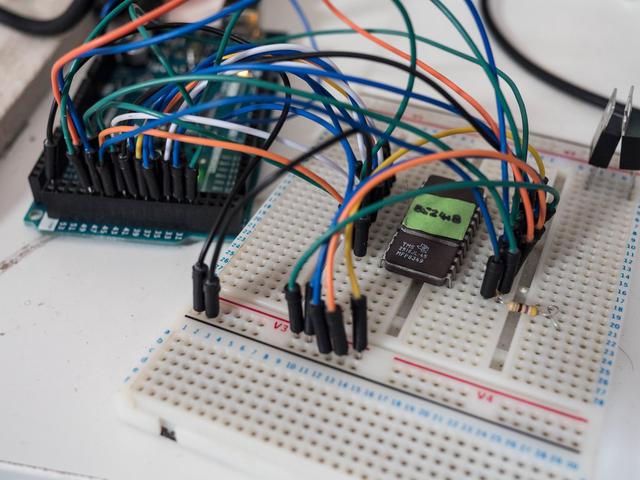
With these in place, I could start wiring up my Arduino Mega. At first I decided to go a little pro and use a Zero Insertion Force (ZIF) socket to make things easier. However, I noticed it wasn't making good contact with my breadboard. I'd get different readings out of the arduino depending on whether or not I pressed down on the socket. That's not great really so I decided to just place the chip directly into the board. It seemed to work better, as repeated reads came out the same.
Some of the pins have to be brought to ground or set at 5V. In both cases, CS and PGM/PG were pulled down to ground, whereas anything with a V in the name was taken up to +5V.
Here is the arduino code, modified from the one I downloaded off the Oddbloke Geek site. It seems to work quite well. If you don't have an Arduino mega you can use a shift register with a normal arduino instead.
/*
ROM Reader. Quick Arduino program to read a parallel-accessed ROM and dump it to the serial
port in hex.

Oddbloke. 16th Feb 2014.
 */

// How I've wired the digital pins on my Arduino to the address and data pins on
// the ROM.
static const int kPin_A0  = 30;
static const int kPin_A1  = 31;
static const int kPin_A2  = 32;
static const int kPin_A3  = 33;
static const int kPin_A4  = 34;
static const int kPin_A5  = 35;
static const int kPin_A6  = 36;
static const int kPin_A7  = 37;
static const int kPin_A8  = 38;
static const int kPin_A9  = 39;
static const int kPin_A10 = 29;
//static const int kPin_A11 = 28; // A11 is needed on the 25L32 chips
//static const int kPin_A12 = 37;
//static const int kPin_A13 = 44;

static const int kPin_D0 = 40;
static const int kPin_D1 = 41;
static const int kPin_D2 = 42;
static const int kPin_D3 = 43;
static const int kPin_D4 = 44;
static const int kPin_D5 = 45;
static const int kPin_D6 = 46;
static const int kPin_D7 = 47;

const char hex[] = {'0', '1', '2', '3', '4', '5', '6', '7',
              '8', '9', 'a', 'b', 'c', 'd', 'e', 'f'};

void setup()
{
  // set the address lines as outputs ...
  pinMode(kPin_A0, OUTPUT);
  pinMode(kPin_A1, OUTPUT);
  pinMode(kPin_A2, OUTPUT);
  pinMode(kPin_A3, OUTPUT);
  pinMode(kPin_A4, OUTPUT);
  pinMode(kPin_A5, OUTPUT);
  pinMode(kPin_A6, OUTPUT);
  pinMode(kPin_A7, OUTPUT);
  pinMode(kPin_A8, OUTPUT);
  pinMode(kPin_A9, OUTPUT);
  pinMode(kPin_A10, OUTPUT);
  //pinMode(kPin_A11, OUTPUT);
  //pinMode(kPin_A12, OUTPUT);
  //pinMode(kPin_A13, OUTPUT);

  // set the data lines as inputs ...
  pinMode(kPin_D0, INPUT);
  pinMode(kPin_D1, INPUT);
  pinMode(kPin_D2, INPUT);
  pinMode(kPin_D3, INPUT);
  pinMode(kPin_D4, INPUT);
  pinMode(kPin_D5, INPUT);
  pinMode(kPin_D6, INPUT);
  pinMode(kPin_D7, INPUT);

  Serial.begin(9600);
}

void SetAddress(int addr)
{
  // update the address lines to reflect the address we want ...
  digitalWrite(kPin_A0, (addr & 1)?HIGH:LOW);
  digitalWrite(kPin_A1, (addr & 2)?HIGH:LOW);
  digitalWrite(kPin_A2, (addr & 4)?HIGH:LOW);
  digitalWrite(kPin_A3, (addr & 8)?HIGH:LOW);
  digitalWrite(kPin_A4, (addr & 16)?HIGH:LOW);
  digitalWrite(kPin_A5, (addr & 32)?HIGH:LOW);
  digitalWrite(kPin_A6, (addr & 64)?HIGH:LOW);
  digitalWrite(kPin_A7, (addr & 128)?HIGH:LOW);
  digitalWrite(kPin_A8, (addr & 256)?HIGH:LOW);
  digitalWrite(kPin_A9, (addr & 512)?HIGH:LOW);
  digitalWrite(kPin_A10, (addr & 1024)?HIGH:LOW);
  //digitalWrite(kPin_A11, (addr & 2048)?HIGH:LOW);
  //digitalWrite(kPin_A12, (addr & 4096)?HIGH:LOW);
  //digitalWrite(kPin_A13, (addr & 8192)?HIGH:LOW);
}

byte ReadByte()
{
  // read the current eight-bit byte being output by the ROM ...
  byte b = 0;
  if (digitalRead(kPin_D0)) b |= 1;
  if (digitalRead(kPin_D1)) b |= 2;
  if (digitalRead(kPin_D2)) b |= 4;
  if (digitalRead(kPin_D3)) b |= 8;
  if (digitalRead(kPin_D4)) b |= 16;
  if (digitalRead(kPin_D5)) b |= 32;
  if (digitalRead(kPin_D6)) b |= 64;
  if (digitalRead(kPin_D7)) b |= 128;

  return(b);
}

void loop()
{
  byte d[16];
  int x, y, addr;

  // The only reason I'm choosing to read in blocks of 16 bytes
  // is to keep the hex-dump code simple. You could just as easily
  // read a single byte at a time if that's all you needed.

  Serial.println("Reading ROM ...\n");

  //for (addr = 0; addr < 4096; addr += 16) // for the 25L32-45 chips
  for (addr = 0; addr < 2048; addr += 16) // for D2716 / TMS2516
  {
    // read 16 bytes of data from the ROM ...
    for (x = 0; x < 16; x++)
    {
      SetAddress(addr + x); // tells the ROM the byte we want ...
      d[x] = ReadByte(); // reads the byte back from the ROM
    }

    // now we'll print each byte in hex ...
    for (y = 0; y < 16; y++)
    {
      Serial.print(hex[ (d[y] & 0xF0) >> 4  ]);
      Serial.print(hex[ (d[y] & 0x0F)       ]);
    }

    // and print an ASCII dump too ...

    /*Serial.print(" ");
    for (y = 0; y < 16; y++)
    {
      char c = '.';
      if (d[y] > 32 && d[y]<127) c = d[y];
      Serial.print(c);
    }*/

    Serial.print("\n");
  }

  // All done, so lockup ...
  while (true) {delay(10000);}
}
This code prints out human readable HEX in neat formatting. That's useful for us to eyeball but we need to do some more conversion in order to do a proper analysis.
The next step is do a quick conversion of the hex dumps, into their proper ones and zeroes so I can see what is in them. There's a good chance I might not have read them correctly, but I'm hoping that somewhere in these ROM dumps is some English ASCII text I can pull out, which should tell me I'm on the right track. I'm hoping there are some fonts in there as well, which would be fun to play with.
Once I've got something more solid, I'll post it all up on github. If you have any idea on how to repair and hack around an electron microscope, do get in touch with the hacdc folks.