So I'm getting married. Not something I ever thought would occur but it's happening! I'm very excited! A big adventure is about to start (and not just the wedding - more on that in the coming months). Since we are both nerds, my fiancee and I wanted some sort of nerdy aspect to our wedding and we figured that the invite itself was the best thing to work on. It allows for a few of our family and good friends to get in on the action and it's a little more interesting than just a paper slip. It's something you can keep and modify after the event.
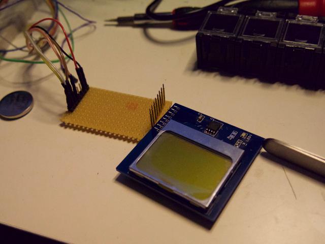
The design is based around the nokia 5110 screen and the ATtiny85 chip. I've generally been an AVR type person as oppose to PIC or the like, due to the arduino background I have. I wanted to use a screen and my good friend charles mentioned the 5110. They are cheap and pleasingly retro which ticks two boxes. Not only that, but you can use SPI to talk to it, so its really easy to link with the ATtiny. I've used a few different SPI libs in projects before such as the Doorbell I put together a few years back. With the basics in mind, I started by breadboarding the design using a 5110 breakout board and a through-hole version of the chip. The final design would use surface mount (as I generally prefer soldering that way).
The trick with this design is keeping the cost low, the design easy to solder and still have the boards finished before the end of November. In the end, thanks to the pound plummeting against the dollar, we had a few issues with sourcing screens from China. I used Alibaba to contact a Chinese supplier, paying extra for the faster shipping. Some of the screens had duff connectors and I reckon I could have done better by just going with eBay. Rather than go with DirtyPCB as I usually do, I asked Quick-Teck to manufacture the boards. Whilst they cost more (and the delivery time was about the same) they are based in the UK and they check over the boards for you. I felt this was worth it because we had to have the boards work first time.
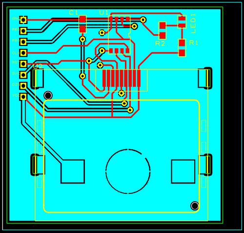
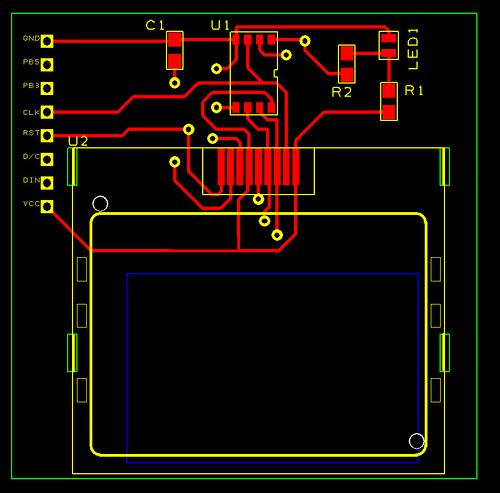
I used Designspark to design my boards. I had to convert an EAGLE footprint of the 5110 board I found into designspark format, but fortunately this is not so hard. I'm still undecided which program I like the best - both have pros and cons. The tricky parts of the board are not the electrical bit, but the physical connections required to 'snap' the screen into place. The connection has to be good for the screen to work. Now the invites are out, I can say that this connection was probably the hardest bit. That, and the initial problem I had in flashing the chip.
I spent a long time wondering why my buspirate would not flash the chip? People told me that I needed decoupling capacitors (in analysing the board, I noticed a mistake with resistor R2 but lets just gloss over that). In the end, this wasn't the problem. It was the fact that the breakout pin holes were not making a solid connection with the programmer. I used header pins soldering in for the first few boards to confirm this, and then settled on some pogo pins to program the rest. It's always good to check and double check all the things. In fact, this is probably the most difficult thing, for me personally. Making sure the little foam connector on the screens is the right way around was another gotcha. The 5110 uses a small, foam like connector that has one side looking blank (ish) and the other with the 9 darker looking connections. Some of the screens had this foam connector inserted the wrong way.
Soldering everything up didn't take too long once I got the hang of it. I could manage about 10 per hour which seemed alright to me. Surface mount soldering I find much easier than through-hole. You just need the right solder (leaded for sure!), a flux pen and a decent pair of tweezers. A small box with lids can hold your parts in order so you don't have to faff with the wrappers when you are assembling and using plenty of solder on battery clip joints is key. Solder wick is handy if you end up joining the legs of a chip together but with the right amount of flux this rarely occurs.
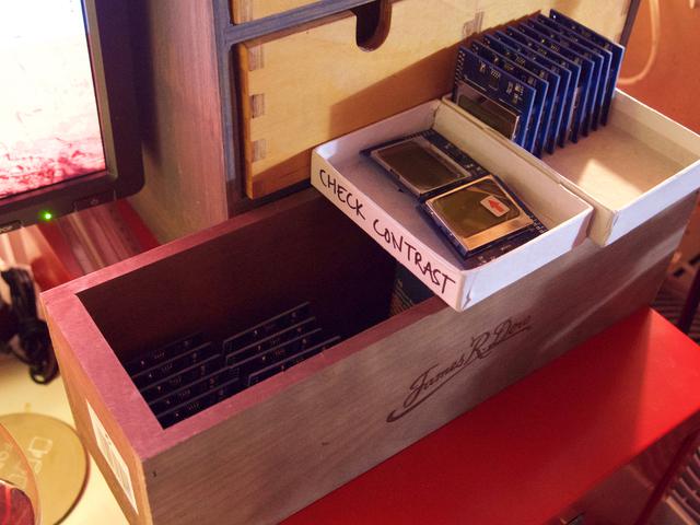
The software is mostly based on the work by this chap. I modified it, and adapted various segments, cut out what wasn't needed and added some functions and tests of my own. Another issue we had after flashing the chips was to do with contrast. I uploaded the classic 'hello-word-blinky-led' program to the boards, just to make sure they actually worked and ran code. They did but the screens were still blank. Turns out they weren't blank - they just had the contrast turned way down in the light end. Altering that in code and checking connections seemed to work.
The whole thing is up on github and is fairly straightforward to play with, if you are into this sort of thing. It's a cheap way to get 8K worth of functionality onto a screen with low power and cost requirements. I suspect I'll end up using the remaining screens for a few silly projects after the wedding no doubt. I think a few Snake and Tetris clones might be required at the very least.